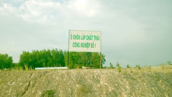
Waste Containment Pit
The Industrial and Hazardous Waste Recycling and Treatment Plant project is designed, constructed, and operated using a complete process and advanced technology to maximize the efficiency of waste recycling and treatment—from the point of generation to final disposal. To address the current environmental issues in the locality, the project owner has planned the construction of containment pits for the final disposal of wastes that can no longer be reused or recycled, thereby contributing to thorough environmental pollution control.
Design of Industrial Waste Containment Pits
The waste collected and treated in the containment pits consists of the residual material left after the recycling process at the plant, allowing for proactive management. After classification and recycling, non-recyclable waste will be safely stored in the waste storage facility. Once the volume of non-hazardous industrial waste awaiting landfill reaches the required amount for one containment pit (7,500 tons over 5 years), it will be transported by specialized vehicles to the non-hazardous industrial waste pit for disposal during the dry season. The construction of the waste pits will be carried out sequentially. The construction plan for the industrial waste containment pits is presented in Table 1.16.
Table 1.16: Construction Plan for Industrial Waste Containment Pits
| No. |
Code |
Waste Accumulation Period (Before Treatment) |
Expected Construction Year |
Accumulated Time |
| 1 |
CN 1 |
Aug/2012 – 2020 |
2020 |
7 years 4 months |
| 2 |
CN 2 |
2021 – 2026 |
2026 |
5 years |
| 3 |
CN 3 |
2027 – 2032 |
2032 |
5 years |
| 4 |
CN 4 |
2033 – 2038 |
2038 |
5 years |
| 5 |
CN 5 |
2039 – 2044 |
2044 |
5 years |
| 6 |
CN 6 |
2045 – 2050 |
2050 |
5 years |
| 7 |
CN 7 |
2051 – 2056 |
2056 |
5 years |
| 8 |
CN 8 |
2057 – 2062 |
2062 |
5 years |
Source: Investment Project, 2012.
The non-hazardous waste containment pit is designed according to the standards shown in Table 1.17.
Table 1.17: Design Standards for Industrial Waste Containment Pits
| No. |
Description |
Technical Specification |
Notes |
| 1 |
Number of operational days per year |
300 days/year |
Used to calculate annual waste quantity |
| 2 |
Annual amount of stored waste awaiting treatment |
1,500 tons/year |
Stored in the interim storage area before transferring to landfill |
| 3 |
Number of years to fill one waste containment pit |
5 years |
Each containment pit is used once every 5 years |
| 4 |
Total waste amount needing treatment over 5 years |
7,500 tons |
Used as the design basis for each containment pit |
| 5 |
Volume of waste treated over 5 years (based on 0.7 tons/m³) |
10,714 m³ |
Corresponding to 5 years' waste volume processed in one pit |
| 6 |
Surface area of a single containment cell |
670 m² |
- |
Source: Investment Project, 2012.
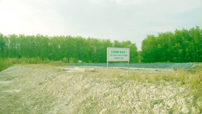
To ensure secondary environmental issues are minimized during the final treatment of industrial waste, the containment pits will be constructed with full liner systems in accordance with design standards.
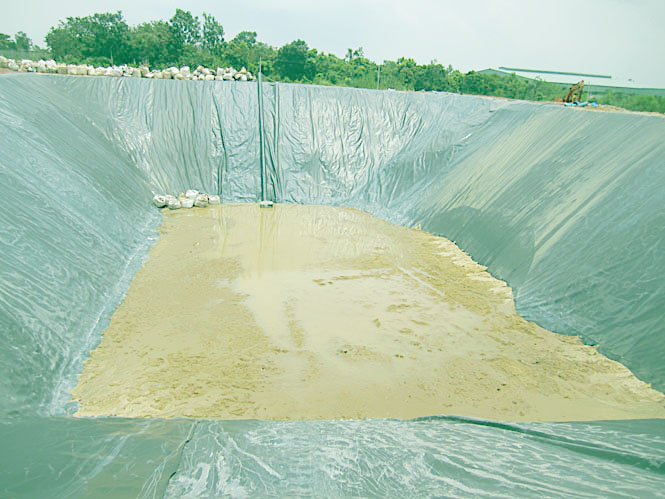
Bottom Liner System
The liner system includes a dual-layer bottom and side wall structure with two drainage layers, each consisting of:
-
Compacted existing soil (natural foundation);
-
0.3 m thick compacted clay layer (permeability coefficient k = 10⁻⁷ cm/s);
-
2 mm thick HDPE (High-Density Polyethylene) impermeable liner;
-
0.3 m thick drainage sand layer (permeability coefficient k = 0.9);
-
Geotextile fabric layer.
Drainage Layer
The waste containment pits are also equipped with a main drainage line running along the length of the pits. Branch lines collect leachate and direct it to the main line, which then leads to a collection sump. From there, leachate is pumped to the plant's wastewater treatment facility.
Sedimentation pits are installed every 180–200 m along the pipe system to prevent blockages. These pits are brick-built, waterproof, and measure 800 mm × 800 mm × 800 mm. Leachate collection pipes have a smooth inner surface and a diameter of 150 mm, with 10 mm perforations along their entire length. The drainage system is illustrated in the provided diagram.
If the plant operates at maximum capacity, an average of 5 tons of industrial waste is treated daily.
Hazardous Waste Treatment Area
The hazardous waste containment pits are designed to receive hazardous waste (mainly generated from the plant) that is inert and cannot be recycled or treated through thermal, chemical, or biological methods. The hazardous waste area is divided into pits similar to those used for non-hazardous industrial waste.
Hazardous waste pits are used for final disposal of hazardous waste types or waste exceeding the threshold levels defined by QCVN 07:2009 – the National Technical Regulation on Hazardous Waste Thresholds issued by the Ministry of Natural Resources and Environment. Prior to final disposal, the hazardous waste is treated, stabilized, solidified, and safely stored in temporary storage facilities. Once a sufficient quantity is accumulated, construction of the waste pits proceeds sequentially, and disposal is carried out during the dry season.
1) Basic Design Parameters
Hazardous waste containment pits are planned and designed according to the following principles:
-
Waste compaction is calculated based on a bulk density of 800 kg/m³;
-
Pit utilization efficiency is 80%;
-
Each pit is designed to be filled within 5 years. Given the variability in industrial waste volumes over the years, the design is phased to ensure consistency.
The design standards are presented in Table 1.18: Design Standards for Hazardous Waste Containment Pits.
| No. |
Description |
Technical Specification |
Notes |
| 1 |
Number of operational days per year |
300 days/year |
Used for calculating the amount of waste |
| 2 |
Annual waste volume stored while awaiting treatment |
1,500 tons/year |
Stored in an interim area until enough waste accumulates for 1 pit |
| 3 |
Number of years to fill one containment pit |
5 years |
One full waste treatment every 5 years |
| 4 |
Total waste volume processed in 5 years |
7,500 tons |
Basis for constructing one containment pit |
| 5 |
Volume of waste (based on 0.7 tons/m³) for 5 years |
9,375 m³ |
Total volume accumulated over 5 years for one pit |
| 6 |
Average surface area of one containment pit |
500 m² |
- |
Source: Investment Project, 2012.
2) Construction Plan for Hazardous Waste Containment Pits
The construction plan for industrial waste containment pits is presented in Table 1.19.
Table 1.19: Construction Plan for Industrial Waste Containment Pits
| No. |
Pit Code |
Storage Period for Waste Awaiting Treatment |
Estimated Construction Year |
Accumulated Waste Storage Duration |
| 1 |
NH 1 |
Aug/2012 – 2020 |
2020 |
7 years 4 months |
| 2 |
NH 2 |
2021 – 2026 |
2026 |
5 years |
| 3 |
NH 3 |
2027 – 2032 |
2032 |
5 years |
| 4 |
NH 4 |
2033 – 2038 |
2038 |
5 years |
| 5 |
NH 5 |
2039 – 2044 |
2044 |
5 years |
| 6 |
NH 6 |
2045 – 2050 |
2050 |
5 years |
| 7 |
NH 7 |
2051 – 2056 |
2056 |
5 years |
| 8 |
NH 8 |
2057 – 2062 |
2062 |
5 years |
Source: Investment Project, 2012.
3) Technical Construction Specifications
a) Double-Layer Bottom and Side Wall Liner Structure
The pit bottom is designed with a double-layer liner system. The structure of this system includes:
-
Compacted existing soil (natural subgrade);
-
0.3 m thick compacted clay layer (permeability coefficient k = 10⁻⁷ cm/s);
-
2 mm thick HDPE (High-Density Polyethylene) impermeable liner;
-
0.3 m thick drainage sand layer (permeability coefficient k = 0.9);
-
Geotextile fabric layer.
b) Leachate Collection System Structure
Each waste containment pit is equipped with two leachate collection systems, including the following layers:
The leachate collection piping system of each pit is designed with the following requirements:
-
One or more main pipelines run along the slope direction of the pit. Branch lines direct leachate to the main line. The main line conveys leachate to a sump, where it is pumped or directly routed to the leachate treatment facility.
-
A sedimentation pit is installed every 180–200 m along each pipe to prevent blockages. These pits are typically built with bricks and have waterproof structures. Each pit measures 800 mm × 800 mm × 800 mm.
-
Leachate collection pipes must have a smooth inner surface and a diameter of no less than 150 mm. The pipes are perforated with 10–20 mm holes along their length, with the perforated area accounting for 10–15% of the pipe surface.
The leachate collection system must ensure chemical and mechanical durability throughout the operating life of the pit. The slope of each pipeline depends on the pit's bottom terrain but should not be less than 2% for branch lines and 1% for main lines. The leachate collection layer must be at least 30 cm thick and meet the following criteria: at least 5% of the mass consisting of particles ≤ 0.075 mm, and a permeability coefficient K ≤ 10⁻² cm/s. The closer the material is to the collection pipe, the coarser the particle size should be, to prevent fine sand particles from clogging the system while still allowing gravity drainage to the collection system.
Collected leachate (if any) will be treated at the leachate treatment system (HTXLCL) and then pumped to the main wastewater treatment facility (HTXLNTTT) of the plant. The quality of treated wastewater must meet the Vietnamese technical standards according to QCVN 25:2009/BTNMT, Column A and QCVN 40:2011/BTNMT, Column A.